A Potentiometer, often called a "pot," is a simple and versatile electrical component used to measure and control a circuit's voltage (or potential difference). It is commonly used in various electrical and electronic devices and in physics and engineering experiments. In an NCERT Class 12 Physics context, a potentiometer is often taught as part of practical experiments studying electrical circuits and their characteristics. Here are the key aspects and functions of a potentiometer in Class 12 Physics.
Potentiometer: Working Principle
A potentiometer consists of a resistive wire, usually made of a uniform material with a high resistance per unit length, such as nichrome. The wire is wound onto a non-conductive material, and it has a sliding contact, called the wiper or slider, that can move along its length. The two ends of the wire are connected to a voltage source, typically a battery.
Potentiometer: Measuring Voltage
The primary function of a potentiometer is to measure an unknown voltage (or potential difference) by comparing it to a known voltage. When the slider is moved along the wire, it creates a variable voltage divider. The voltage at the wiper position is compared to the voltage across the entire wire, and the unknown voltage can be determined by adjusting the slider position until the voltage at the wiper equals the known voltage.
Balanced Potentiometer
A potentiometer is considered "balanced" when the voltage at the wiper (Vw) is equal to the known voltage (V) across the entire wire. In this state, the potentiometer is said to be calibrated, and you can use it to measure the unknown voltage.
Potentiometer: Measurement Procedure
To measure an unknown voltage using a potentiometer, you would follow these steps:
- Connect the known voltage source (battery) to the two ends of the potentiometer wire.
- Connect the unknown voltage source or component in the circuit in such a way that its potential difference can be compared with the potentiometer's voltage.
- Adjust the slider until the voltage at the wiper equals the known voltage. This condition is met when there is no current flowing through the potentiometer (i.e., it's balanced).
- Measure the length of the wire from one end to the slider. This length represents the fraction of the total wire length (L) at which the unknown voltage is equivalent to the known voltage.
- Use the fraction of the wire length to calculate the unknown voltage, usually employing the formula:
Unknown Voltage = (Fractional Length / Total Length) * Known Voltage
Potentiometer: Applications
Potentiometers are used in various applications, including:
- Volume controls in audio equipment.
- Dimmer switches for lights.
- Calibration of voltage sources.
- Measurement of internal resistance of a battery.
- Temperature measurement using resistance-temperature detectors (RTDs).
In Class 12 Physics experiments, students often work with potentiometers to understand the concept of potential dividers, calibration, and measurement techniques for voltage and internal resistance of cells. Potentiometers are valuable tools in laboratory work, offering precise control and measurement of voltages.
FAQs on Potentiometer
Q. In a potentiometer arrangement, a cell of emf 1.25 V gives a balance point at 35.0 cm length of the wire. If the cell is replaced by another cell and the balance point shifts to 63.0 cm, what is the emf of the second cell?
EMF of the cell, = 1.25 V
Let the EMF of the replaced cell be
Existing balance point, = 35 cm
New balance point, = 63 cm
From the relation of balance condition, we get
= , we get = = = 2.25 V
Therefore the emf of the another cell is 2.25V
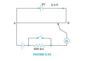
Q. Figure 3.33 shows a potentiometer with a cell of 2.0 V and internal resistance 0.40 Ω maintaining a potential drop across the resistor wire AB. A standard cell which maintains a constant emf of 1.02 V (for very moderate currents up to a few mA) gives a balance point at 67.3 cm length of the wire. To ensure very low currents drawn from the standard cell, a very high resistance of 600 kΩ is put in series with it, which is shorted close to the balance point. The standard cell is then replaced by a cell of unknown emf ϵ and the balance point found similarly, turns out to be at 82.3 cm length of the wire. (a) What is the value e ? (b) What purpose does the high resistance of 600 kΩ have? (c) Is the balance point affected by this high resistance? (d) Would the method work in the above situation if the driver cell of the potentiometer had an emf of 1.0V instead of 2.0V? (e) Would the circuit work well for determining an extremely small emf, say of the order of a few mV (such as the typical emf of a thermo-couple)? If not, how will you modify the circuit?

- Constant emf of the standard cell, = 1.02 V
Balance point on the wire, = 67.3 cm
A cell of unknown emf, , replaced the standard cell. Therefore, new balance point on the wire, l = 82.3 cm.
The relation of connected emf and balance point is,
=
Hence, 1.247 V
- The purpose of using high resistance of 600 KΩ is to reduce the current through the galvanometer when the movable contact is far from the balance point.
- The balance point is not affected by the presence of high resistance.
- The point is not affected by the internal resistance of the driver cell.
- The method would not work if the emf of the driver cell of the potentiometer had an emf of 1.0 V instead of 2.0 V. This is because if the emf of the driver cell of the potentiometer is less than the emf of the other cell, then there would be no balance point on the wire.
- The circuit would not work well for determining an extremely small emf. As the circuit would be unstable, the balance point would be close to end A. Hence, there would be a large percentage of error.
The given circuit can be modified if a series resistance is connected with the wire AB. The potential drop across AB is slightly greater than the emf measured. The percentage error would be small.
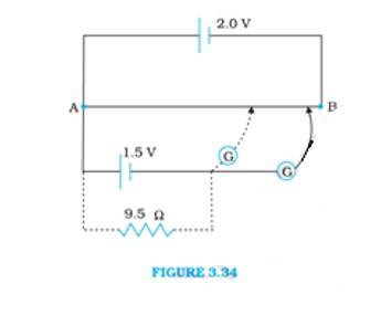
Q. Figure 3.34 shows a 2.0 V potentiometer used for the determination of internal resistance of a 1.5 V cell. The balance point of the cell in open circuit is 76.3 cm. When a resistor of 9.5 Ω is used in the external circuit of the cell, the balance point shifts to 64.8 cm length of the potentiometer wire. Determine the internal resistance of the cell.

Internal resistance of the cell = r
Balance point of the cell in open circuit, = 76.3 cm
An external resistance ® is connected to the circuit with R = 9.5 Ω
New balance point of the circuit, = 64.8 cm
Current flowing through circuit = I
The relation connecting resistance and emf is,
r = R = 1.69 Ω
Therefore, the internal resistance is 1.69 Ω.
News & Updates
Current Electricity Exam
Student Forum
Popular Courses After 12th
Exams: BHU UET | KUK Entrance Exam | JMI Entrance Exam
Bachelor of Design in Animation (BDes)
Exams: UCEED | NIFT Entrance Exam | NID Entrance Exam
BA LLB (Bachelor of Arts + Bachelor of Laws)
Exams: CLAT | AILET | LSAT India
Bachelor of Journalism & Mass Communication (BJMC)
Exams: LUACMAT | SRMHCAT | GD Goenka Test
